Le Trung Thang 2011
Prepare tools:
- Hardware: AT91SAM7S EVALUATION BOARD and Jlink 7 (http://www.segger.com) debug board (see schematic at below).
Other alternation can be considered in case of you don’t have AT91SAM7S Evaluation Board could be OLIMEX SAM7-P256 Development Board (www.olimex.com).
I have not tested with Olimex board yet, but strong belive that it's able to work well with this demonstration project.
 |
| Fig 1. AT91SAM7S EVALUATION BOARD |
 | |
 |
 |
| Fig 4. AT91SAM7S EVALUATION BOARD and Jlink v7 |
- AT91SAM7S EVALUATION BOARD schematic:
- OLIMEX SAM7-P256 Development Board Schematic
- JLink v7 debug board schematic: ( Download Jlink v7 full resource)
AT91SAM7S256 is a microcontroller from Atmel company based on the 32-bit ARM 7-TDMI architecture.
IAR Embedded Workbench for ARM is IDE including C/C++ compiler, assembler, linker, editor, project manager for ARM processor.
 |
| Fig 5. IAR Embedded Workbench |
In this article, I assume that you have already had basic knowledge about the ARM 7 core architecture, C/C++ language and a little knowledge about the Hardware which to help you can read the schematic of evaluation board. Because the heart of evaluation board is AT91SAM7S256 MCU, so you also must read the data sheet of the AT91SAM7S256 to be able to understand the operation of board.
First, we need to take at glance at the IAR tool suite. The IAR Embedded Workbench for ARM is a IDE for developing embedded system applications based on ARM platform. IAR supplies all things you need to make a complete project. IAR supports a wide range of different ARM cores as ARM7, ARM9, Cortex... In this article, i use a existing AT91SAM7S project from Atmel, so you don't need create a new project. Instead of that, you just need to modify this project to fix to the our evaluation board.
AT91SAM7S family is a SoC (System on Chip) developed by Atmel based on ARM7TDMI core.
After complete IAR Embedded Workbench for ARM installation, download source code and go to the directory: \Atmel\at91sam7s-ek\getting-started-project and open file getting-started-project.eww to start program (Fig 5).
2. Linker configuration file
In Workspace at the left of window, expand all the sub nodes of the node at91lib, go to the leaf at91sam7s256 and double click to the file flash.icf (Fig 6).
| ||

The flash.icf is the linker configuration file. To link and locate an application in memory according to your requirements, Linker needs information about how to handle sections and how to place them into the available memory regions. In other words, Linker needs a configuration, passed to it by means of the linker configuration file.
A section is a logical entity containing a piece of data or code that should be placed at a physical location in memory. A section can be placed either in RAM or in ROM. In a normal embedded application, sections that are placed in RAM do not have any content, they only occupy space.
Compiler create the sections and the linker will base on linker configuration file to link them together.
A section always has a name and a attribute associate with it. The section name is any name while the section attribute has 4 kinds: readonly code, readonly data, readwrite code, readwrite data.
If you only use readonly keyword instead of readonly code , the IAR linker will process in both readonly code and readonly data section.
In AT91SAM7s256, the ROM (FLASH) memory spans from 0x00100000 to 0x0013FFFF and the RAM memory spans from 0x00200000 to 0x0020FFFF. The beginning memory address 0x00000000 can be RAM or FLASH depend on your configuration (see data sheet AT91SAM7S256). In order to declare AT91SAM7S256 memory map to the IAR linker, we declare in linker configuration file as following:
define symbol __ICFEDIT_region_ROM_start__ = 0x100000;
define symbol __ICFEDIT_region_ROM_end__ = 0x13FFFF;
define symbol __ICFEDIT_region_RAM_start__ = 0x200000;
define symbol __ICFEDIT_region_RAM_end__ = 0x20FFFF;
define symbol __ICFEDIT_region_ROM_end__ = 0x13FFFF;
define symbol __ICFEDIT_region_RAM_start__ = 0x200000;
define symbol __ICFEDIT_region_RAM_end__ = 0x20FFFF;
define memory mem with size = 4G;
define region STA_region = mem:[from __ICFEDIT_region_ROM_start__ size __ICFEDIT_size_startup__];
define region ROM_region = mem:[from __ICFEDIT_region_ROM_start__+__ICFEDIT_size_startup__ to __ICFEDIT_region_ROM_end__];
define region VEC_region = mem:[from __ICFEDIT_region_RAM_start__ size __ICFEDIT_size_vectors__];
define region RAM_region = mem:[from __ICFEDIT_region_RAM_start__+__ICFEDIT_size_vectors__ to __ICFEDIT_region_RAM_end__];
With the above definitions, we declared 4 regions: STA_region, ROM_region, VEC_region, RAM_region. A region is a set of non-overlapping memory ranges. In each region, we can place on it the sections. With these 4 regions, we fulfilled whole of the AT91SAM7S256 memory.
When the application is running, it needs to use the stack memory area for its operation. In ARM 7 core, there are total of 6 stack memory areas corresponding to the 7 modes operation of CPU.
In there, the System mode and User mode shared a common stack memory area together. All other modes use the stack memory areas of their own. Name and size of these stacks must be supplied to compiler by declaring as following:
Immediately after reset, CPU is on Supervisor mode. So, we need create a stack memory area associate with this mode. However, as you can see in the start-up code in the next section, due to reducing memory space consumption, we might don't need this stack memory area.
In the above declaration, we created 3 stack blocks: CSTACK, SVC_STACK, IRQ_STACK.
CSTACK: is used for User and System mode. SVC_STACK: is used for Supervisor mode and IRQ_STACK is used for interrupt mode.
We also need create the heap memory with name is HEAP for dynamic memory allocation.
After defines Regions and Sections, we need to place the sections to the declared regions. It note that besides definition sections in linker configuration file, we also can define the sections in the assembly start-up code which stores start-up code of the application. The declaration piece following will place the sections to the regions respectively.
When the application is running, it needs to use the stack memory area for its operation. In ARM 7 core, there are total of 6 stack memory areas corresponding to the 7 modes operation of CPU.
In there, the System mode and User mode shared a common stack memory area together. All other modes use the stack memory areas of their own. Name and size of these stacks must be supplied to compiler by declaring as following:
define symbol __ICFEDIT_size_startup__ = 0x100;
define symbol __ICFEDIT_size_vectors__ = 0x100;
define symbol __ICFEDIT_size_cstack__ = 0x1000;//size user & system mode
define symbol __ICFEDIT_size_svcstack__ = 0x60; // size Supervisor mode
define symbol __ICFEDIT_size_irqstack__ = 0x60; // size interrupt mode
define symbol __ICFEDIT_size_heap__ = 0x60; // size heap memory
define block CSTACK with alignment = 8, size = __ICFEDIT_size_cstack__ { };
define block SVC_STACK with alignment = 8, size = __ICFEDIT_size_svcstack__ { };
define block IRQ_STACK with alignment = 8, size = __ICFEDIT_size_irqstack__ { };
define block HEAP with alignment = 8, size = __ICFEDIT_size_heap__ { };
Immediately after reset, CPU is on Supervisor mode. So, we need create a stack memory area associate with this mode. However, as you can see in the start-up code in the next section, due to reducing memory space consumption, we might don't need this stack memory area.
In the above declaration, we created 3 stack blocks: CSTACK, SVC_STACK, IRQ_STACK.
CSTACK: is used for User and System mode. SVC_STACK: is used for Supervisor mode and IRQ_STACK is used for interrupt mode.
We also need create the heap memory with name is HEAP for dynamic memory allocation.
After defines Regions and Sections, we need to place the sections to the declared regions. It note that besides definition sections in linker configuration file, we also can define the sections in the assembly start-up code which stores start-up code of the application. The declaration piece following will place the sections to the regions respectively.
place in STA_region { section .cstartup }; //this section declare in start-up code
place in ROM_region { readonly};
place in VEC_region { section .vectors }; // this section declare in start-up code
place in RAM_region {readwrite, block IRQ_STACK, block SVC_STACK, block CSTACK, block HEAP };
place in ROM_region { readonly};
place in VEC_region { section .vectors }; // this section declare in start-up code
place in RAM_region {readwrite, block IRQ_STACK, block SVC_STACK, block CSTACK, block HEAP };
With the above definitions, we placed all the sections to the 4 declared regions. In that, we placed .vectors section which stores interrupt vector table and interrupt handler to beginning address of RAM memory. In addition, we also placed .cstartup section which stores the program entry point to beginning address of ROM memory.
As the above mentioned, two sections: .vector and .cstartup weren't declared in the linker configuration file but were declared in the assembly start-up code which you will see below. Besides the sections was created by user, the IAR compiler also creates the sections for it's own, for example: .text, .bss,... section.
In order to place the sections to the regions, we can use the directive place in region_name {section}, in there, section can be name of section or attribute of section.
Example:
- place in ROM_region { readonly}; This directive put to ROM_region region all the sections which have the attribute is readonly.
- place in RAM_region {readwrite}; This directive put to RAM_region region all the sections which have the attribute is readwrite.
- place in STA_region { section .cstartup }; This directive put to STA_region region the section has name is .cstartup.
The readonly sections usually store the program code while the readwrite sections usually store the program data. Because we want the program run on ROM, so we should place readonly sections to the ROM_region. Of course, readwrite sections must be placed to the RAM_region since they store the program data as global variants, static variants, ...
If you want whole of program run on RAM then you need put readonly sections to the RAM_region instead of placing us to the ROM_region.
In summary, IAR linker does offer a lot of helpful way in your program optimization.
In the following is 3 examples corresponding to 3 scenarios to allocate the application to memory.
a. All code run in ROM (file flash.icf in the project).
/*-Memory Regions-*/
define symbol __ICFEDIT_region_ROM_start__ = 0x100000;
define symbol __ICFEDIT_region_ROM_end__ = 0x13FFFF;
define symbol __ICFEDIT_region_RAM_start__ = 0x200000;
define symbol __ICFEDIT_region_RAM_end__ = 0x20FFFF;
/*-Sizes-*/
define symbol __ICFEDIT_size_startup__ = 0x100;
define symbol __ICFEDIT_size_vectors__ = 0x100;
define symbol __ICFEDIT_size_cstack__ = 0x1000;
define symbol __ICFEDIT_size_svcstack__ = 0x60;
define symbol __ICFEDIT_size_irqstack__ = 0x60;
define symbol __ICFEDIT_size_heap__ = 0x60;
/*-Exports-*/
export symbol __ICFEDIT_region_ROM_start__;
export symbol __ICFEDIT_region_ROM_end__;
export symbol __ICFEDIT_region_RAM_start__;
export symbol __ICFEDIT_region_RAM_end__;
export symbol __ICFEDIT_size_startup__;
export symbol __ICFEDIT_size_vectors__;
export symbol __ICFEDIT_size_cstack__;
export symbol __ICFEDIT_size_svcstack__;
export symbol __ICFEDIT_size_irqstack__;
export symbol __ICFEDIT_size_heap__;
/**** End of ICF editor section. ###ICF###*/
define memory mem with size = 4G;
define region STA_region = mem:[from __ICFEDIT_region_ROM_start__ size __ICFEDIT_size_startup__];
define region ROM_region = mem:[from __ICFEDIT_region_ROM_start__+__ICFEDIT_size_startup__ to __ICFEDIT_region_ROM_end__];
define region VEC_region = mem:[from __ICFEDIT_region_RAM_start__ size __ICFEDIT_size_vectors__];
define region RAM_region = mem:[from __ICFEDIT_region_RAM_start__+__ICFEDIT_size_vectors__ to __ICFEDIT_region_RAM_end__];
define block CSTACK with alignment = 8, size = __ICFEDIT_size_cstack__ { };
define block SVC_STACK with alignment = 8, size = __ICFEDIT_size_svcstack__ { };
define block IRQ_STACK with alignment = 8, size = __ICFEDIT_size_irqstack__ { };
define block HEAP with alignment = 8, size = __ICFEDIT_size_heap__ { };
initialize by copy { readwrite};
initialize by copy { section .vectors };
do not initialize { section .noinit };
place in STA_region { section .cstartup };
place in ROM_region { readonly};
place in VEC_region { section .vectors };
place in RAM_region {readwrite, block IRQ_STACK, block SVC_STACK, block CSTACK, block HEAP };
b. All code run in RAM (file sram.icf in the project).
/*-Memory Regions-*/
define symbol __ICFEDIT_region_RAM_start__ = 0x200000;
define symbol __ICFEDIT_region_RAM_end__ = 0x20FFFF;
/*-Sizes-*/
define symbol __ICFEDIT_size_vectors__ = 0x100;
define symbol __ICFEDIT_size_cstack__ = 0x1000;
define symbol __ICFEDIT_size_svcstack__ = 0x60;
define symbol __ICFEDIT_size_irqstack__ = 0x60;
define symbol __ICFEDIT_size_heap__ = 0x0;
/*-Exports-*/
export symbol __ICFEDIT_region_RAM_start__;
export symbol __ICFEDIT_region_RAM_end__;
export symbol __ICFEDIT_size_vectors__;
export symbol __ICFEDIT_size_cstack__;
export symbol __ICFEDIT_size_svcstack__;
export symbol __ICFEDIT_size_irqstack__;
export symbol __ICFEDIT_size_heap__;
/**** End of ICF editor section. ###ICF###*/
define memory mem with size = 4G;
define region VEC_region = mem:[from __ICFEDIT_region_RAM_start__ size __ICFEDIT_size_vectors__];
define region RAM_region = mem:[from __ICFEDIT_region_RAM_start__+__ICFEDIT_size_vectors__ to __ICFEDIT_region_RAM_end__];
define block CSTACK with alignment = 8, size = __ICFEDIT_size_cstack__ { };
define block SVC_STACK with alignment = 8, size = __ICFEDIT_size_svcstack__ { };
define block IRQ_STACK with alignment = 8, size = __ICFEDIT_size_irqstack__ { };
define block HEAP with alignment = 8, size = __ICFEDIT_size_heap__ { };
do not initialize { section .noinit };
place in VEC_region { section .vectors };
place in RAM_region { section .cstartup, readonly, readwrite, block IRQ_STACK, block SVC_STACK, block CSTACK, block HEAP };
c. Copy all Code from ROM to RAM and run application in RAM (file copy code to RAM.icf in the project).
/*-Memory Regions-*/
define symbol __ICFEDIT_region_ROM_start__ = 0x100000;
define symbol __ICFEDIT_region_ROM_end__ = 0x13FFFF;
define symbol __ICFEDIT_region_RAM_start__ = 0x200000;
define symbol __ICFEDIT_region_RAM_end__ = 0x20FFFF;
/*-Sizes-*/
define symbol __ICFEDIT_size_startup__ = 0x100;
define symbol __ICFEDIT_size_vectors__ = 0x100;
define symbol __ICFEDIT_size_cstack__ = 0x1000;
define symbol __ICFEDIT_size_sysstack__ = 0x60;
define symbol __ICFEDIT_size_irqstack__ = 0x60;
define symbol __ICFEDIT_size_heap__ = 0x60;
/*-Exports-*/
export symbol __ICFEDIT_region_ROM_start__;
export symbol __ICFEDIT_region_ROM_end__;
export symbol __ICFEDIT_region_RAM_start__;
export symbol __ICFEDIT_region_RAM_end__;
export symbol __ICFEDIT_size_startup__;
export symbol __ICFEDIT_size_vectors__;
export symbol __ICFEDIT_size_cstack__;
export symbol __ICFEDIT_size_sysstack__;
export symbol __ICFEDIT_size_irqstack__;
export symbol __ICFEDIT_size_heap__;
/**** End of ICF editor section. ###ICF###*/
define memory mem with size = 4G;
define region STA_region = mem:[from __ICFEDIT_region_ROM_start__ size __ICFEDIT_size_startup__];
define region ROM_region = mem:[from __ICFEDIT_region_ROM_start__+__ICFEDIT_size_startup__ to __ICFEDIT_region_ROM_end__];
define region VEC_region = mem:[from __ICFEDIT_region_RAM_start__ size __ICFEDIT_size_vectors__];
define region RAM_region = mem:[from __ICFEDIT_region_RAM_start__+__ICFEDIT_size_vectors__ to __ICFEDIT_region_RAM_end__];
define block CSTACK with alignment = 8, size = __ICFEDIT_size_cstack__ { };
define block SYS_STACK with alignment = 8, size = __ICFEDIT_size_sysstack__ { };
define block IRQ_STACK with alignment = 8, size = __ICFEDIT_size_irqstack__ { };
define block HEAP with alignment = 8, size = __ICFEDIT_size_heap__ { };
initialize by copy { readwrite, section .text};
initialize by copy { section .vectors };
do not initialize { section .noinit };
place in STA_region { section .cstartup };
place in ROM_region { ro};
place in VEC_region { section .vectors };
place in RAM_region {readwrite, block IRQ_STACK, block SYS_STACK, block CSTACK, block HEAP };
3. System Start-up code
In all embedded systems, system startup code is executed to initialize the system—both the hardware and the software system—before the main function of the application is called. The CPU imposes this by starting execution from a fixed memory address.
As an embedded software developer, you must ensure that the startup code is located at the dedicated memory addresses, or can be accessed using a pointer from the vector table. This means that startup code and the initial vector table must be placed in non-volatile memory, such as ROM, EPROM, or flash.
As an embedded software developer, you must ensure that the startup code is located at the dedicated memory addresses, or can be accessed using a pointer from the vector table. This means that startup code and the initial vector table must be placed in non-volatile memory, such as ROM, EPROM, or flash.
In the start-up code, we have 2 sections: .vectors section and .cstartup section.
.vector section holes interrupt vector and interrupt pre-processor. The interrupt pre-processor will be executed immediately after an interrupt event occurs. The interrupt pre-processor will do some tasks as backup CPU current status, changes CPU mode to Interrupt mode…before program actually enters the interrupt handler. To speed-up response speed of the interrupt handler we should copy this section to RAM where data accessing is faster ROM.
.cstartup section holds start-up code which will be executed first immediately after resets CPU. For programs don’t use Real Time OS, the start-up code will have 3 basic tasks consist of:
- Initializes hardware modules necessary for the operating of CPU, for example: init clock frequency, setup memory controller, setup interrupt controller… depending on hardware organization of each Chip manufacturer.
- Setups the stack pointer for CPU operation mode as stack pointer for interrupt mode, stack pointer for system mode,…
- Initializes the components need to initialize of program, for example: static variants, global variants and any sections need to be initialized.
Because start-up code holds entry-point of program, so .cstartup section need to be placed in the region which has beginning logical address is 0x000000. When CPU reset, it always fetches the instruction at logical address 0x000000, and then memory controller will map this logical address to corresponded physical address where actually holds the code program. In AT91SAM7S256, the physical address of ROM begins from 0x100000 and RAM from 0x200000. The address 0x000000 is either ROM or RAM depending on remapping. Immediately after power on or full reset, the address 0x000000 is mapped to ROM address, so when CPU fetches the instruction from 0x000000, then an instruction from 0x100000 will be returned.
Because start-up code holds entry-point of program, so .cstartup section need to be placed in the region which has beginning logical address is 0x000000. When CPU reset, it always fetches the instruction at logical address 0x000000, and then memory controller will map this logical address to corresponded physical address where actually holds the code program. In AT91SAM7S256, the physical address of ROM begins from 0x100000 and RAM from 0x200000. The address 0x000000 is either ROM or RAM depending on remapping. Immediately after power on or full reset, the address 0x000000 is mapped to ROM address, so when CPU fetches the instruction from 0x000000, then an instruction from 0x100000 will be returned.
After completes its own operation, start-up code will go to the main function to continue executing as a normal C/C++ program.
4. Go to the main function
After finished the system start-up operation, program will go into the main function which is the C/C++ application entry point.
4.1 Re-direct function Printf :
  /* ----------------------------------------------------------------------------
  *         ATMEL Microcontroller Software Support
  * ----------------------------------------------------------------------------
  * Copyright (c) 2008, Atmel Corporation
  *
  * All rights reserved.
  *
  * Redistribution and use in source and binary forms, with or without
  * modification, are permitted provided that the following conditions are met:
  *
  * - Redistributions of source code must retain the above copyright notice,
  * this list of conditions and the disclaimer below.
  *
  * Atmel's name may not be used to endorse or promote products derived from
  * this software without specific prior written permission.
  *
  * DISCLAIMER: THIS SOFTWARE IS PROVIDED BY ATMEL "AS IS" AND ANY EXPRESS OR
  * IMPLIED WARRANTIES, INCLUDING, BUT NOT LIMITED TO, THE IMPLIED WARRANTIES OF
  * MERCHANTABILITY, FITNESS FOR A PARTICULAR PURPOSE AND NON-INFRINGEMENT ARE
  * DISCLAIMED. IN NO EVENT SHALL ATMEL BE LIABLE FOR ANY DIRECT, INDIRECT,
  * INCIDENTAL, SPECIAL, EXEMPLARY, OR CONSEQUENTIAL DAMAGES (INCLUDING, BUT NOT
  * LIMITED TO, PROCUREMENT OF SUBSTITUTE GOODS OR SERVICES; LOSS OF USE, DATA,
  * OR PROFITS; OR BUSINESS INTERRUPTION) HOWEVER CAUSED AND ON ANY THEORY OF
  * LIABILITY, WHETHER IN CONTRACT, STRICT LIABILITY, OR TORT (INCLUDING
  * NEGLIGENCE OR OTHERWISE) ARISING IN ANY WAY OUT OF THE USE OF THIS SOFTWARE,
  * EVEN IF ADVISED OF THE POSSIBILITY OF SUCH DAMAGE.
  * ----------------------------------------------------------------------------
  */

 /*
     IAR startup file for AT91SAM7S microcontrollers.
  */

         MODULE  ?cstartup

        ;; Forward declaration of sections.
        SECTION IRQ_STACK:DATA:NOROOT(2)
        SECTION CSTACK:DATA:NOROOT(3)

//------------------------------------------------------------------------------
//         Headers
//------------------------------------------------------------------------------

#define __ASSEMBLY__
#include "board.h"

//------------------------------------------------------------------------------
//         Definitions
//------------------------------------------------------------------------------

#define ARM_MODE_ABT     0x17
#define ARM_MODE_FIQ     0x11
#define ARM_MODE_IRQ     0x12
#define ARM_MODE_SVC     0x13
#define ARM_MODE_SYS     0x1F
#define ARM_MODE_USER    0x10 // Thang's comment

#define I_BIT            0x80
#define F_BIT            0x40

//------------------------------------------------------------------------------
//         Startup routine
//------------------------------------------------------------------------------

/*
    Exception vectors
*/
         SECTION .vectors:CODE:NOROOT(2)

       PUBLIC  resetVector
       PUBLIC  irqHandler

       EXTERN  Undefined_Handler
       EXTERN  SWI_Handler
       EXTERN  Prefetch_Handler
       EXTERN  Abort_Handler
       EXTERN  FIQ_Handler

         ARM

 __iar_init$$done:               // The interrupt vector is not needed
                                 // until after copy initialization is done

 resetVector:
       // All default exception handlers (except reset) are
       // defined as weak symbol definitions.
       // If a handler is defined by the application it will take precedence.
       LDR     pc, =resetHandler        // Reset
       LDR     pc, Undefined_Addr    // Undefined instructions
       LDR     pc, SWI_Addr            // Software interrupt (SWI/SYS)
       LDR     pc, Prefetch_Addr       //Prefetch abort
       LDR     pc, Abort_Addr          // Data abort
       B       .                          // RESERVED
       LDR     pc, =irqHandler         //IRQ
       LDR     pc, FIQ_Addr           // FIQ

 Undefined_Addr: DCD   Undefined_Handler
 SWI_Addr:       DCD   SWI_Handler
 Prefetch_Addr:  DCD   Prefetch_Handler
 Abort_Addr:     DCD   Abort_Handler
 FIQ_Addr:       DCD   FIQ_Handler

 /*
    Handles incoming interrupt requests by branching to the corresponding
   handler, as defined in the AIC. Supports interrupt nesting.
  */
 irqHandler:
         /* Save interrupt context on the stack to allow nesting */
         SUB     lr, lr, #4 //backup return address
         STMFD   sp!, {lr} //copy lr to stack and update sp value,for nesting int
         MRS     lr, SPSR
         STMFD   sp!, {r0, lr} //backup r0 and SPSR for nesting int

         /* Write in the IVR to support Protect Mode */
         LDR     lr, =AT91C_BASE_AIC // lr = 0xFFFFF000, base address of AIC
         LDR     r0, [r14, #AIC_IVR] //read INT handler address
         STR     lr, [r14, #AIC_IVR] // support protect mode

        /* Branch to interrupt handler in system mode */
   MSR     CPSR_c, #ARM_MODE_SYS //  _c in CPSR_c is mean that only control bits is effected
// see: "armasm: Use of MRS and MSR instructions", http://infocenter.arm.com/help/index.jsp?topic=/com.arm.doc.faqs/1472.html
   STMFD   sp!, {r1-r3, r4, r12, lr} // backup banked regs & lr of system mode
   MOV     lr, pc // backup return address
   BX      r0 // goto INT handler, before branch, we need to backup the PC reg value
   LDMIA   sp!, {r1-r3, r4, r12, lr} // restore context after complete the INT handler
   MSR   CPSR_c, #ARM_MODE_IRQ | I_BIT //change to INT mode again and disable a new INT

    /* Acknowledge interrupt */
     LDR     lr, =AT91C_BASE_AIC
     STR     lr, [r14, #AIC_EOICR] //notify that finished the INT handler

    /* Restore interrupt context and branch back to calling code */
     LDMIA   sp!, {r0, lr}
     MSR     SPSR_cxsf, lr
     LDMIA   sp!, {pc}^ // return the address of the previous routine, the routine may be a INT handler
                //has lower priority or a normal user program


 /*
   After a reset, execution starts here, the mode is ARM, supervisor
   with interrupts disabled.
   Initializes the chip and branches to the main() function.
  */
        SECTION .cstartup:CODE:NOROOT(2)

         PUBLIC  resetHandler
         EXTERN  LowLevelInit
         EXTERN  ?main
         REQUIRE resetVector
         ARM

 resetHandler:

         /* Set pc to actual code location (i.e. not in remap zone) */
        LDR     pc, =label

        /* Perform low-level initialization of the chip using LowLevelInit() */
 label:
         LDR     r0, =LowLevelInit // SuperVisor mode temporarily use the CSTACK to init low level system
         LDR     r4, =SFE(CSTACK) // SFE = Section end
         MOV     sp, r4 // SP = R13_Svc
         MOV     lr, pc
         BX      r0

         /* Set up the interrupt stack pointer. */
         MSR     cpsr_c, #ARM_MODE_IRQ | I_BIT | F_BIT  // Change the mode
         LDR     sp, =SFE(IRQ_STACK) // sp = r13_irq

        /* Set up the SYS stack pointer. */
         MSR     cpsr_c, #ARM_MODE_SYS | F_BIT   // Change the mode and enable INT
         LDR     sp, =SFE(CSTACK) // sp = r13

        /* Branch to main() */
         LDR     r0, =?main
         MOV     lr, pc
         BX      r0

         /* Loop indefinitely when program is finished */
 loop4:
         B       loop4
         END
board_cstartup_iar.s
After finished the system start-up operation, program will go into the main function which is the C/C++ application entry point.
4.1 Re-direct function Printf :
In C standard library, printf function defined as be to load data from the given locations and writes them to the standard output stdout according to control of the
formatter. In C/C++ standard library, stdout is a standard output device: the Screen.
However, in many embedded systems, sometimes printf function will not play in tradition manner. Our project is an example.
In our project, instead printf will push a string to the screen, it will write data to serial port. So, stdout is now serial port. To do this, we need re-direct function printf.
In applications attach in OS, stdout was ready-made the low-level functions which will handle writing data to stdout. Actually, stdout does not hold the low-level functions by itself. Instead of that, it holds the File descriptor, is an integer number which will be mapped to the actual functions.
And in its own task, printf will call to the lower functions: fprintf -> vfprintf ->... putchar -> … -> write in order. Final, the write function will base on File descriptor to call low-level function which actual writes data to device. (get more: C/C++ Input Output Stream).
In applications none OS, the low-level functions are not often existing. This is mean that the write function has not implemented yet. File descriptor is only formality. So, to re-direct function printf, we have to implement function write. The write function can be implemented based on either File descriptor or not, this depends on the different systems.
In our project, instead of implementing the write function, we implemented higher level function: putchar. The putchar function is stored in file dbgu.c of the project.
Be noticed that because function putchar is a standard library function, so it also predefined in the prebuilt libraries shipped within IAR compiler. However, putchar in prebuilt libraries is a weak function, this is mean that if application developer defines a new putchar function in his project then this redefined function has higher priority.
The putchar function defined in file dbgu.c as following:
// Outputs a character on the DBGU.
// param: c  Character to output.
// return The character that was output.
//------------------------------------------------------------------------------
signed int putchar(signed int c)
{
    return fputc(c, stdout);
}
fputc then will find out function DBGU_PutChar which actually sends a character to serial port. There are 2 serial ports in AT91SAM7S256, one thing belongs to Debug Unit block and other thing belongs to USART block. The Printf function associates with Debug Unit block.// Outputs a character on the DBGU line.
// note: This function is synchronous (i.e. uses polling).
// param: c Character to send.
//------------------------------------------------------------------------------
void DBGU_PutChar(unsigned char c)
{
// Wait for the transmitter to be ready
while ((AT91C_BASE_DBGU->DBGU_CSR & AT91C_US_TXEMPTY) == 0);
// Send character
AT91C_BASE_DBGU->DBGU_THR = c;
// Wait for the transfer to complete
while ((AT91C_BASE_DBGU->DBGU_CSR & AT91C_US_TXEMPTY) == 0);
}
Of course, before can send data to the output device, we need configure Debug Unit block suitably. This presented in the macro TRACE_CONFIGURE(DBGU_STANDARD, 115200, BOARD_MCK) in main function. 4.2 Configuration for other peripherals
In this demo project, in addition to Debug Unit (DBGU) module, we will discover more 4 familiar modules: Parallel Input/Output Controller (PIO), Periodic Interval Timer (PIT), Timer Counter (TC) and Advanced Interrupt Controller (AIC).
This module controls all input/output operation of physical Pins of MCU. Moreover, it also controls connection between the other modules as PIT, TC… to the physical Pin.
In AT91SAM7S family, at a time, any physical Pin in list of 32 input/output lines can enable any particular module to connect to it.
The functional modules, as PIO, TC, DBGU … are grouped into 2 groups: Peripheral A and Peripheral B. It can imagine this is analogous with the term Namespace in C++ programming language. However, the different point is in AT91SAM7S one any functional module can belong to both of groups Peripheral A and Peripheral B. For example: The module Pulse Width Modulation Controller (PWM) is belonging to both Peripheral A and Peripheral B. |
| Fig 7. PIO module. Source: Atmel |
Before you want to use any physical Pins, you need configure them properly.
// Configures a list of Pin instances, each of which can either hold a single
// pin or a group of pins, depending on the mask value; all pins are configured
// by this function. The size of the array must also be provided and is easily
// computed using PIO_LISTSIZE whenever its length is not known in advance.
// param list  Pointer to a list of Pin instances.
// param size  Size of the Pin list (calculated using PIO_LISTSIZE).
// return 1 if the pins have been configured properly; otherwise 0.
//---------------------------------------------------------------------------

unsigned char PIO_Configure(const Pin *list, unsigned int size)
{
    // Configure pins
    while (size > 0) {
        switch (list->type) {
            case PIO_PERIPH_A:
                PIO_SetPeripheralA(list->pio,
                                   list->mask,
                                   (list->attribute & PIO_PULLUP) ? 1 : 0);
                break;
            case PIO_PERIPH_B:
                PIO_SetPeripheralB(list->pio,
                                   list->mask,
                                   (list->attribute & PIO_PULLUP) ? 1 : 0);
                break;
            case PIO_INPUT:
                AT91C_BASE_PMC->PMC_PCER = 1 << list->id;//cho phep clock PIO
                PIO_SetInput(list->pio,
                             list->mask,
                             (list->attribute & PIO_PULLUP) ? 1 : 0,
                             (list->attribute & PIO_DEGLITCH)? 1 : 0);
                break;
            case PIO_OUTPUT_0:
            case PIO_OUTPUT_1:
                PIO_SetOutput(list->pio,
                              list->mask,
                              (list->type == PIO_OUTPUT_1),
                              (list->attribute & PIO_OPENDRAIN) ? 1 : 0,
                              (list->attribute & PIO_PULLUP) ? 1 : 0);
                break;
            default: return 0;
        }
        list++;
        size--;
    }
    return 1;
}
In function PIO_Configure, the highlight is that it used the Pin structure. This is a good idea of Object Oriented Thinking. A physical Pin is now treated as a Pin object within properties properly. Now, the application developer doesn’t need to know in the physical details of Pins, they are simply to use Pin Struct and function PIO_Configure whenever they want to configure operation of physical Pins. The lesson: Write in C/C++ but think in Object Oriented Programming manner.
The struct Pin was predefined in file pio.h as following:
// Describes the type and attribute of one PIO pin or a group of similar pins.
// The #type# field can have the following values:
//    - PIO_PERIPH_A
//    - PIO_PERIPH_B
//    - PIO_OUTPUT_0
//    - PIO_OUTPUT_1
//    - PIO_INPUT
//
// The #attribute# field is a bitmask that can either be set to PIO_DEFAULt,
// or combine (using bitwise OR '|') any number of the following constants:
//    - PIO_PULLUP
//    - PIO_DEGLITCH
//    - PIO_OPENDRAIN
//---------------------------------------------------------------------------

typedef struct {
    // Bitmask indicating which pin(s) to configure.
    unsigned int mask;
    // Pointer to the PIO controller which has the pin(s).
    AT91S_PIO    *pio;
    // Peripheral ID of the PIO controller which has the pin(s).
    unsigned char id;
    // Pin type.
    unsigned char type;
    // Pin attribute.
    unsigned char attribute;
} Pin;
In our project, we configured to 2 Pins PA17 and PA18 as out pins for 2 Leds. Two Pins PA19 and PA20 are for 2 buttons. See in board schematic for details.
- Periodic Interval Timer (PIT) Module
The PIT aims at providing periodic interrupts for use by operating systems. It is same a timer/counter block but with higher accuracy. More details please see in the datasheet.
To configure the PIT Module, we use function ConfigurePit in file main.c.
In our project, we used the PIT and its interrupt to create the time-stamp which supports to DEBOUNCE of buttons.
- Timer Counter (TC) Module
AT91SAM7S256 features three identical 16-bit Timer Counter channels. In our project, we only use Timer/counter 0 to generate a timer interrupt every 250ms. Each of every 250ms, a timer interrupt trigger will be created. This interrupt will change current status of LED 2 (pin PA17) from on to off and otherwise.
The LED 1 (pin PA18) will be toggled its status by a snippet code in main function.
To configure and start the TC module, we can use function TC_Configure and TC_Start in the file tc.c.
In addition, we also used two the buttons for stopping or starting operation of 2 LEDs. Button 1 (pin PA 20) will control LED 1 operation and Button 2 (pin PA19) is for LED 2.
- Advanced Interrupt Controller (AIC) Module
To be able to understand the AIC module, in addition to study of AT91SAM7S256 datasheet you also need to understand the interrupt mechanism of core ARM7.
The ARM7 core exposes two interrupt lines: normal interrupt (nIRQ) and fast interrupt (nFIQ) and each of the interrupt types has a set of the particular assistant registers. Setting up for AIC module is quite complex because this setting concerns to setup interrupt of ARM core as well.
The following instructions are simplified steps in setup AIC module from start to end: - Setup the interrupt of core: Enable core interrupt, create stack for interrupt mode… These presented in label resetHandler in file board_cstartup_iar.s.
- Create an interrupt handler entry which runs first as soon as an interrupt occurs. This presented in label irqHandler in file board_cstartup_iar.s. In optional, you should un-stack the interrupt hardware stack of AIC module. This presented in function LowLevelInit in file board_lowlevel.c.
- Configuration interrupt source of desired modules. To configure interrupt source of these modules, we use function AIC_ConfigureIT in file aic.c. For instance, configuration for interrupt source of the PIT module will be: AIC_ConfigureIT(AT91C_ID_SYS, AT91C_AIC_PRIOR_LOWEST, ISR_Pit). Here: ISR_Pit is the interrupt routine of PIT module. This routine will service as soon as PIT interrupt event occurs.
- Enable AIC and interrupt function of the related module.
 |
| Fig 8. AIC module. Source: Atmel |
The conditions for an interrupt goes on and serviced is:
- Interrupt must be enabled at core level.
- An interrupt trigger occurred from a certain source.
- The interrupt function of corresponded module must be enabled.
- This interrupt must have the highest priority.
Notice that there are two terms to descript about the status of an interrupt: Pending and interrupted.
A pending interrupt is an interrupt has never been serviced. This occurs when an interrupt event happens but its priority is lower the priority of current interrupt. So, it waits for higher interrupts complement. Its interrupt status will be certain memorized in the peripheral block which spawned interrupt event. The Pending interrupt cannot be pushed into the hardware stack.
An interrupted interrupt is the interrupt was serviced but has not completed yet. It was interrupted by another interrupt having higher priority. Hence, its ID and priority was pushed into the hardware stack.
In general, it’s only interrupts which are either running or interrupted to be able pushed into the hardware stack.
If an interrupt has priority is lower current interrupt. It will be pending until all higher priority interrupts were serviced. This is mean that after current interrupt finished, the pending interrupt will be compared with interrupts in the hardware stack and which interrupt has highest priority will be picked up for running . More details, you can look up in the datasheet, however.
Follow is the function to configure an interrupt in the AIC module:
// Configures an interrupt in the AIC. The interrupt is identified by its
// source (AT91C_ID_xxx) and is configured to use the specified mode and
// interrupt handler function. Mode is the value that will be put in AIC_SMRx
// and the function address will be set in AIC_SVRx.
// The interrupt is disabled before configuration, so it is useless
// to do it before calling this function. When AIC_ConfigureIT returns, the
// interrupt will always be disabled and cleared; it must be enabled by a
// call to AIC_EnableIT().
// param source  Interrupt source to configure.
// param mode  Triggering mode and priority of the interrupt.
// param handler  Interrupt handler function.
//---------------------------------------------------------------------

void AIC_ConfigureIT(
    unsigned int source,
    unsigned int mode,
    void (*handler)(void))
{
    // Disable the interrupt first
    AT91C_BASE_AIC->AIC_IDCR = 1 << source;

    // Configure mode and handler
    AT91C_BASE_AIC->AIC_SMR[source] = (mode);
    AT91C_BASE_AIC->AIC_SVR[source] = (unsigned int) handler;

// Clear interrupt
AT91C_BASE_AIC->AIC_ICCR = 1 << source;//xoa interrupt source, =>have no INT peding
}
 |
| Fig 9. External Interrupt Source Input Stage. Source: Atmel |
4.3 Completion main function
Finally, after completed all configurations, our main function are simply to call the related configuration functions and then go on to the forever while loop which holds the snippet code for continuously changing status of LED 1.
//---------------------------------------------------------------------------
// Application entry point. Configures the DBGU, PIT, TC0, LEDs and buttons
// and makes LED\#1 blink in its infinite loop, using the Wait function.
// return Unused (ANSI-C compatibility).
//---------------------------------------------------------------------------

int main(void)
{
    // DBGU configuration
    TRACE_CONFIGURE(DBGU_STANDARD, 115200, BOARD_MCK);
    printf("-- Getting Started Project %s --\n\r", SOFTPACK_VERSION);
    printf("-- %s\n\r", BOARD_NAME);
    printf("-- Compiled: %s %s --\n\r", __DATE__, __TIME__);

    // Configuration
    ConfigurePit(); // config PIT module
    ConfigureTc(); // config TC module
    ConfigureButtons(); // config 2 buttons
    ConfigureLeds(); // config 2 LEDs
    // Main loop
    while (1) {

        // Wait for LED to be active
      while (!pLedStates[0]); // this is analogous a flag variable

        // Toggle LED state if active
        if (pLedStates[0]) {

            LED_Toggle(0); // toggle current status LED 1 (pin PA18)
            printf("1"); //ThangLe add, for test
        }

        // Wait for 500ms
        Wait(500);
    }
}
4.4 Conclusion
Although this project is only a getting started project but it demonstrated you many interesting topics as using the DBGU module, PIT module, TC module and special is leaning about how to use AIC module.
In addition, organization of source code and coding will help you, if you are an electronics engineer, become familiar with new way of thinking: Write in C/C++ but think in Object Oriented Programming manner.
5. Using J-Link
J-link debugger supports real time debug via a plug-in integrating with IAR. J-link supplies also some independent tools to access directly to CPU via physical protocol JTAG.
Configuration for J-link operation in IAR is very easy. After connect and power-on J-link board and Evaluation board as figure 10.  |
| Fig 10. Jlink Debugger and Evaluation Board |
 |
| Fig 11. Setting debugger |
Go to Project -> Download and Debug to debug your program as figure 12 and figure 13.
 |
| Fig 12. Download program to board and start debug |
 |
| Fig 13. Real Time Debug with J-link emulator |
To load execute file (bin or hex) to memory (RAM or Flash), you have two options: using command line in J-Link Commander or using J-Flash ARM.
Using J-Link Commander: Go to Start -> All Program -> SEGGER -> J-Link ARM V4.22a -> J-Link Commander to open J-Link Commander.
Type sequence the three commands as in figure 14 to load the bin file to memory.
 |
| Fig 14. Load the bin file to board |
Using J-Flash ARM: Go to Start -> All Program -> SEGGER -> J-Link ARM V4.22a -> J-Flash ARM to open J-Flash ARM. Go to: Open -> Open data file…
to select a bin or hex file. Enter memory address of RAM or Flash if you selected the bin file and result as figure 15.
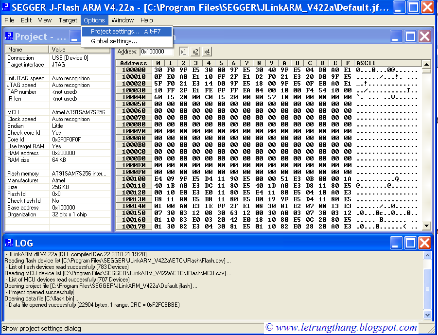 |
| Fig 15. Using J-Flash ARM |
Go to: Option -> Project setting… to configuration for J-Flash ARM as figure 16. Go to: Target -> Connect to connect to board.
 |
| Fig 16. Configuration for J-Flash ARM |
 |
| Fig 17. Load execute file to the board |
In general, using J-Flash ARM is more easy but using J-Link Commander is more flexible.
In addition, if you only want to load your program to the evaluation board, you also can use H-JTAG (www.hjtag.com) as a low cost solution. Although H-JTAG supports hardware debug too but its speed is very low.
= = = =***= = = =***= = = =***= = = =
No comments:
Post a Comment